CAN Data Acquisition: How It Works and Telematics Solutions
CAN Data Acquisition
Operational optimization and the management of modern vehicle fleets rely on absolute mastery of onboard information flows. At the heart of this digital transformation, CAN data acquisition via telematics has established itself as an essential methodology for capturing, centralizing, and leveraging every physical or digital signal in real time.
Whether for the monitoring of industrial vehicles, micro-mobility, or the deployment of car-sharing services, the use of the Controller Area Network (CAN) protocol enables robust, bidirectional, and standardized communication. For fleet managers and R&D teams, deploying the right connected system for remote measurement, control, and diagnostics is a highly strategic challenge.
What Is CAN Data Acquisition?
Definition and Role of the Bus Within a Connected Network
CAN bus data acquisition consists of intercepting, recording, and remotely transmitting the information flowing through the multiplexed communication network of a rolling vehicle. Originally designed to simplify wiring inside each vehicle, this system connects various electronic control units within a single distributed architecture.
Each node in the network can send and receive messages autonomously. The data acquisition and monitoring (DAQ) architecture developed by DUNASYS relies on an intelligent embedded interface to capture this information transmission, enabling its instantaneous centralization without requiring the physical connection of a computer.
From Physical Signal to IoT Frame
In a fleet monitoring or eco-driving process, various sensors continuously measure physical quantities such as temperature, fuel level, speed, or electrical variables such as battery state. These raw analog signals first undergo a conditioning phase before being converted into digital values.
Once this conversion is complete, the embedded control unit encapsulates this data in binary code within a standardized frame. The telematics unit captures these differential voltage signals and transmits them to the cloud, guaranteeing maximum data integrity against external interference.
How the CAN Protocol and Frame Work
The exchange mechanism within the network relies on non-destructive bitwise arbitration. Two logical and physical states characterize transmission on the lines: the dominant state and the recessive state. If multiple systems transmit simultaneously, the node applying a dominant bit takes priority over the recessive level, thereby preventing data collisions on the vehicle bus.
Anatomy of a CAN Frame Used in Fleet Management
A CAN frame is composed of several distinct sections, known as fields, that structure the information useful for telematics:
- The arbitration field (ID): A unique message identifier encoded on 11 bits (standard CAN) or 29 bits (extended CAN). It defines the absolute priority of the frame.
- The control field (DLC): Indicates the number of useful data bytes present in the message (from 0 to 8 bytes).
- The data field: Contains the digitized physical values from each sensor.
- The control field (CRC): Dedicated to detecting transmission errors to secure the system.
The Evolution Toward Connected CAN FD Systems
To meet the complexity of modern applications and hybrid or electric vehicle architectures, the CAN FD (Flexible Data-rate) standard brings key innovations. It increases transfer speed during the transmission phase and extends the payload to up to 64 bytes per frame. DUNASYS smart units integrate this evolution to densify the acquisition of complex signals without saturating the original bus.
Application Areas: Fleet Management and Car Sharing
The integration of high-performance DAQ systems and telematics units meets strict optimization and safety requirements:
- Fleet management and eco-driving: Analysis of driver behavior by correlating bus frames with external voltage measurements or GPS data to reduce TCO.
- Predictive maintenance: Real-time fleet monitoring where the network ensures the instant transmission of alerts and manufacturer error codes before a mechanical or electrical failure occurs.
- Connected car-sharing solutions: The module captures locking data, vehicle status, and interacts with a mobility platform to automate bookings and keyless access.
The DUNASYS Hardware and Software Architecture
Setting up a robust acquisition and transmission chain requires the harmonious interaction of several hardware and software components.
Hardware: The DCar Range
To capture signals and ensure real-time monitoring, DUNASYS designs cutting-edge equipment:
- Telematics units (DCar-E, DCar-S, DCar-E 3W): These hardware units connect directly to the vehicle bus. They integrate strict galvanic isolation to protect the original electronics against voltage spikes and electrical anomalies.
- The DunaIO module: A system configured to retrieve specific data streams in real time and transmit them to a connected interface.
Software and Data Processing
The cloud software and supervision APIs translate the hexadecimal code of received messages, extracting each information field and converting it into understandable values using specific databases:
- DBC files: Indicate to the software the exact bit position and conversion factor of each signal.
- Standardized diagnostic protocols: Support for industry standards such as OBD-II for passenger vehicles and J1939 for heavy machinery and trucks, enabling universal decoding across multi-brand fleets.
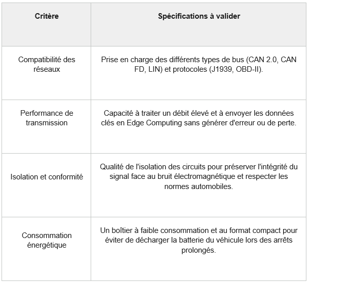
Criteria for Choosing a CAN Acquisition Solution
The choice of tools depends on the type of environment and the constraints of your applications.
Integration and Best Practices for Connected Architecture
To maximize the reliability of your measurement and data transmission architecture:
- Respect network impedance: Integrating a unit onto the bus must never disrupt the line impedance. Poor impedance can alter the original electrical signal.
- Monitor the error rate: An increase in the number of errors is often a sign of an installation fault, an isolation issue, or incorrect configuration of the unit’s reading speed.
- Secure and synchronize data flows: Ensure temporal alignment between the reception of logical frames and GPS data conditioning to guarantee the accuracy of your fleet analysis.
DUNASYS develops comprehensive solutions combining intelligent embedded units and cutting-edge connected platforms. Our hardware solutions and software layers simplify signal processing, sensor management, and the real-time leveraging of your mobility data.
Would you like to connect your fleet or deploy a bespoke car-sharing solution? Discover DUNASYS intelligent solutions.
Questions & Answers
Every message circulating on the bus consists of a sequence of bits. The embedded software or cloud platform uses a configuration file that tells it precisely which field contains the target signal, instantly converting the code into actionable business data.
Electrical isolation protects the connected unit’s communication interface against ground loops and transient overvoltages that are common in vehicle circuits. It prevents physical signal distortion and guarantees the continuity of the telematics solution without risking damage to the original control units.
The protocol has a very strict error management mechanism. If a node detects a non-conformity, it generates an error message. Our units trace these anomalies to help you remotely identify a predictive maintenance issue or a wiring fault on the vehicle.